Hardware Introduction
This section highlights the hardware components used in the project.
Brief information is provided for each component as well as the wiring we used,
with the attached pin descriptions.
Seeeduino Atmega 1280
We haved decided to use Seeeduino Mega Board as our main microcontroller board. The primary features of this board are listed below:
- 70 digital input/output pins (of which 14 can be used as PWM outputs),
- 16 analog inputs,
- 4 UARTs (hardware serial ports),
- a 16 MHz crystal oscillator,
- a USB connection,
- a power jack,
- an ICSP header,
- and a reset button.
[Seeeduino ATMega 1280 PIN Guide & description]
Power
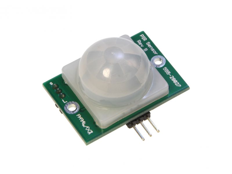
PIR Sensor (#555-28027)
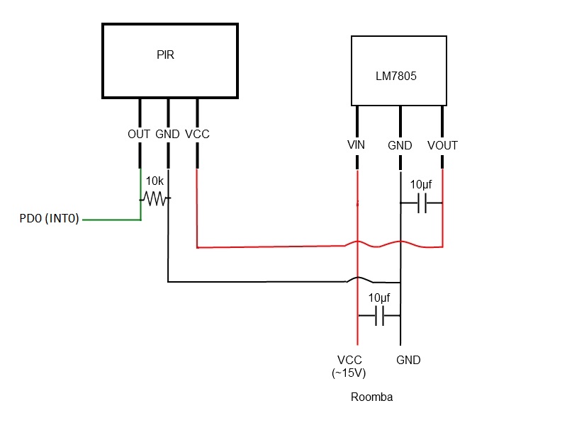
The PIR (Passive Infra-Red) Sensor is a pyroelectric device that detects motion by sensing changes in the infrared (radiant heat) levels emitted by surrounding objects. This motion can be detected by checking for a sudden change in the surrounding IR pattern. When motion is detected the PIR sensor outputs a high signal on its output pin. This logic signal can be read by a microcontroller or used to drive an external load
Wiring
Test Code
#include <avr/interrupt.h>

/* INT0 has the highest priority among interrupts */
/* Port pin PD0 is INT0 for Seeduino Mega */
ISR(INT0_vect)
{
	if ( (EICRA & _BV(ISC00) >> ISC00) &&
		 (EICRA & _BV(ISC01) >> ISC01) )
	{
		/* Enabling interrupt on falling edge */
		PORTA |= _BV(PA3);
		EICRA &= ~_BV(ISC00);
	}else{
		PORTA &= ~_BV(PA3);
		/* Re-enabling interrupt on rising edge */
		EICRA |= _BV(ISC01) | _BV(ISC00);
	}

}

int main()
{
	/* LED output for PIR */
	DDRA |= _BV(PA3);
	/* Enabling external interrupt (INT0) */
	EIMSK |= _BV(INT0);
	/* Enabling rising edge interrupt */
	EICRA |= _BV(ISC01) | _BV(ISC00);
	/* Enabling interrupts globally */
	sei();

	while(1){}
}
pir.c[Datasheet]
UART
#ifndef UART0_H__
#define UART0_H__

void init_uart0(uint8_t);
void uart_print_char(uint8_t);
void uart_print_string(uint8_t [], uint8_t);

#endif
#include <avr/interrupt.h>
#include "uart0.h"

/* Enabling UART0 */
/* See pages 222-231 */
void init_uart0(uint8_t br)
{
	/* Enabling only transfer */
	UCSR0B = _BV(TXEN0);
	/* 8 bit character size */
	UCSR0C = _BV(UCSZ00) | _BV(UCSZ01);
	/* setting baud rate */
	UBRR0 = br;
}

void uart_print_char(uint8_t data)
{
	while (!(UCSR0A & (1 << UDRE0)) ){}
	UDR0 = data;
}

void uart_print_string(uint8_t str[], uint8_t len)
{
	int i;
	for(i = 0; i < len; ++i)
	{
		uart_print_char(str[i]);
	}
}
uart0.h uart0.cHC - SR04 Ultrasonic Range Finder
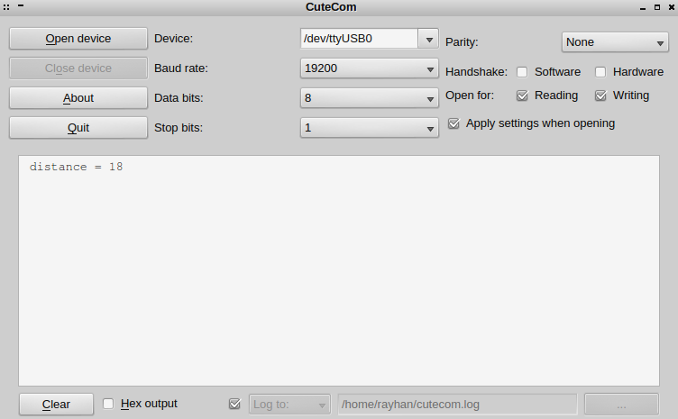
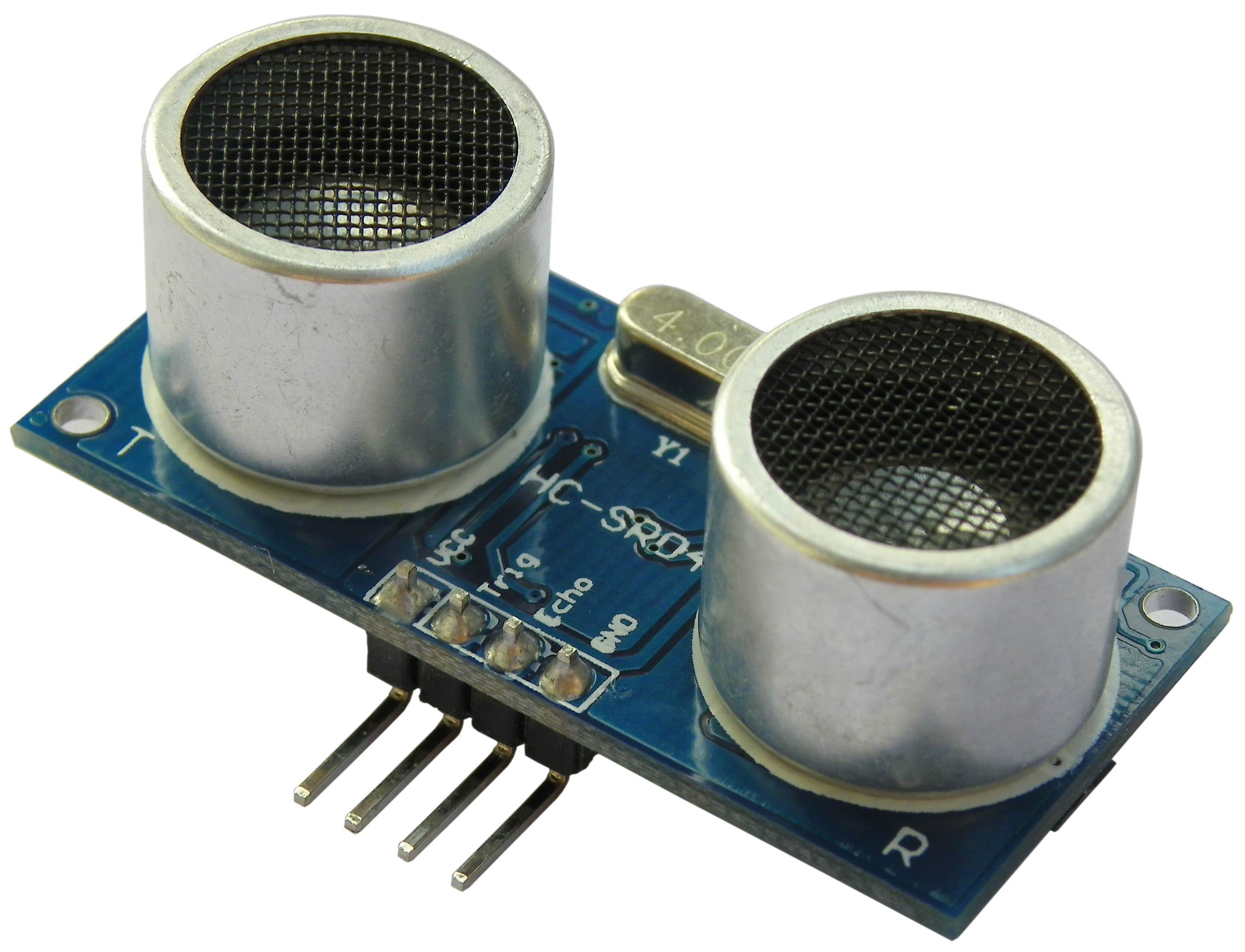
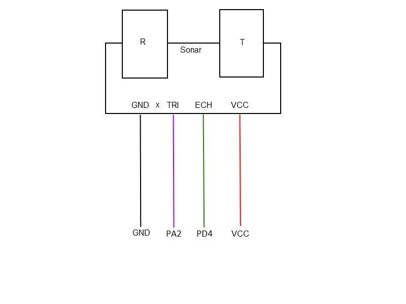
HC-SR04 consists of ultrasonic transmitter,receiver, and control circuits. When trigged it sends out a series of 40KHz ultrasonic pulses and receives echo from an object. The distance between the unit and the object is calculated by measuring the traveling time of sound and output it as the width of a TTLpulse.
Wiring
Test Code
#include <stdlib.h>
#include <string.h>
#include <util/delay.h>
#include <avr/interrupt.h>
#include "uart.h"

volatile uint16_t pulse_start = 0;
volatile uint16_t distance = 0;

/* for printing distance */
char buf[80];

/* Input Capture Unit 1 */
/* Port PD4 (for Seeduino Mega) */
ISR(TIMER1_CAPT_vect)
{
	/* If Rising edge is enabled */
	if ( TCCR1B & _BV(ICES1) ){
		pulse_start = ICR1;
		/* Enabling falling edge detection */
		TCCR1B &= ~_BV(ICES1);
	}else{
		/* speed of sound in air = 34317 cm/s */
		/* ticks per second = 15625 */
		distance = 34317 * (ICR1 - pulse_start) / 15625;
		/* dividing by 2 as echo was received after a round trip */
		distance /= 2;
		/* Re-enabling rising edge detection */
		TCCR1B |= _BV(ICES1);
	}
}

void trigger_sonar()
{
	/* Triggering sonar for 12 micro-seconds */
	PORTA |= _BV(PA2);
	_delay_us(12);
	PORTA &= ~_BV(PA2);
	/* resetting TCNT1 */
	TCNT1 = 0;
}


int main()
{
	/* Setting up trigger pin for the sonar */
	DDRA |= _BV(PA2);
	/* 1064 Prescaler clock (Timer1) */
	/* See page 161 of the attached datasheet */
	TCCR1B 	|= _BV(CS12) | _BV(CS10);
	/* Enabling rising edge detection */
	TCCR1B |= _BV(ICES1);
	/* Enabling edge (input) capture interrupt */
	TIMSK1 |=  _BV(ICIE1);
	/* resetting TCNT1 */
	TCNT1 = 0;
	/* BAUD Rate 51 = 19200 bps */
	/* See page 231 for baud rates in the attached datasheet */
	init_uart(51);
	/* Enabling interrupts globally */
	sei();
	while(1){
		trigger_sonar();
		/* delaying to ensure that echo is received */
		_delay_ms(200);
		/* converting distance (base 10) to string */
		itoa(distance, buf, 10);
		/* printing distance */
		uart_print_string(" distance = ", 12);
		uart_print_string(buf, strlen(buf));

		_delay_ms(10000);
	}
}
sonar.c[Datasheet]
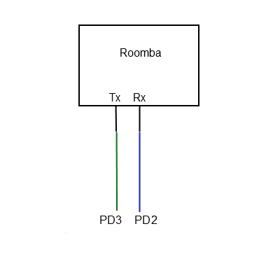
iRobot Roomba Discovery
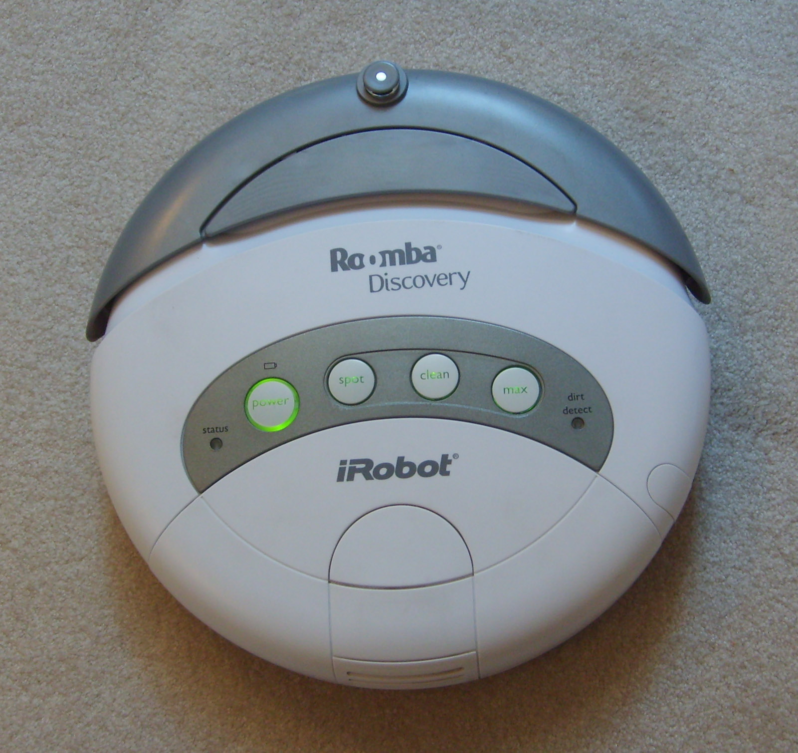
The Roomba from iRobot, is a circular disc shaped vacuum cleaner.Roomba uses a bumper on its front, and when it bumps into a object its brain will tell it in what different direction or pattern to go. Some of these patterns are spiral, wall follow, Z pattern, and random. This technology is known as "AWARE".
Wiring
Test Code
#include <util/delay.h>
#include <avr/interrupt.h>
#include "roomba.h"
#include "uart0.h"

int main()
{
	/* Enabling interrupts globally */
	sei();

	/* Initialize Roomba */
	/* uart is initialized with 19200 bps */
	Roomba_Init();

	/* Roomba sensor data structure */
	/* See senstor_struct.h */
	roomba_sensor_data_t roomba_sensor_data;

	/* Enabling UART0 for printing */
	init_uart0(51);

	while(1){
		/* Driving Roomba straight 200mm/s */
		Roomba_Drive(200, 0x8000);
		_delay_ms(1000);

		/* Getting Roomba (external) sensor data */
		Roomba_UpdateSensorPacket(EXTERNAL, &roomba_sensor_data);
		_delay_ms(250);

		/* Checking if Roomba hit a Vi*rtual wall */
		if (roomba_sensor_data.virtual_wall == 1){
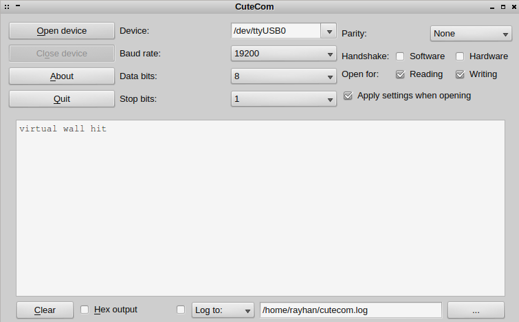
			uart_print_string("virtual wall hit\n", 17);
		}
	}
}
roomba.zip[Specification Manual]
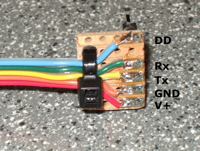
Roomba serial Adapter
All Roombas have a serial connector on them. We will be using this serial port to control and read sensor data from the Roomba. The serial connector is simply an 7-pin Mini-DIN jack with the block in the center.Here DD stands for Device detect,this is a activel low;NC stands for not connected;Rx stands for UART Receiver pin ;Tx for UART transmitter pin;GND for Roomba battery's negative terminal and V+ for Roomba battery's positive terminal.
Complete Parts List
- 1 x ATMega 1280
- 1 x KC7783R PIR Detector Module
- 1 x HC SR04 Ultrasonic Range Finder
- 7 x LEDs
- 2 x 10 µƒ Capacitor
- 1 x 10 kΩ Resistor
- 1 x LM7805 Regulator
- 1 x iRobot Roomba


.jpg)
.jpg)
.jpg)
.jpg)
