Components

In this section we will describe the necessary components for this project. We have identified the following hardware components:
  1. a base-station, and
  2. four satellite-stations.
The purpose of the base-station is to monitor the positions of the satellite stations and inform those stations of their intended trajectories over a short time -- one tenth of a second to be exact. Our expectation is that such frequent monitoring and trajectory correction will enable very precise coordinated motion of the satellite stations.

In this page, we will first list some of the hardware requirements for the two above mentioned components. The specification for some of these components can be found in Hardware Sections of Project 1 and in Project 2. We will then very briefly describe nRF25L01 radios, and Kinect, a depth camera, developed by PrimeSense and Microsoft. In the second part of this section, we will describe software requirements, e.g., the driver, and development environment for Kinect. In the final part, we will describe how these different components communicate and act together to achieve the goal of precise coordinated motion of multiple Roomba robots using a message sequence chart.
Hardware Requirements

We need the following hardware for the base-station:
  1. one micro-controllers,
  2. one nRF24L01 radios,
  3. one Kinect camera, and
  4. one workstation.
Also, we need the following hardware for the four satellite stations:
  1. four Roomba robots,
  2. four micro-controllers,
  3. four nRF24L01 radios,
We have mentioned the specifications for the Roomba and the micro-controller boards in previous projects, namely, in the hardware sections of Project 1 and Project 2. However, this is the first project in this course for which we will use radios, that is, nRF24L01 radios. In addition to the radios, we will also use a Kinect sensor device for the first time in this project. Therefore, we will describe nRF24L01 radios and Kinect sensor device next.

nRF24L01 Radios

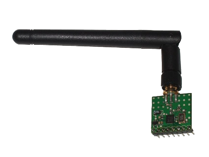
The satellite-stations need to communicate with the base-station to get their speeds and radii every one-tenth of a second. This wireless communication will be facilitated by nRF24L01 radios. The radio communicates with the micro-controller board by the SPI bus. Neil McMillan, our Lab Instructor, kindly provided a driver for this is radio and an implementation of the SPI bus. An excellent description of the inner workings of this radio can be found here -- also written by Neil McMillan. He also provided an example of how to use this radio. The example can be found here. However, the example was written in Arduino. Nevertheless, it is very clear from this example what one needs to do to communicate between two radio devices. Having pointed out a good on-line (and one-stop) resource for nRF24L01 radios, we conclude our discussion on the specification of this radio as Neil has done a remarkable job in his blog.


Figure 1:An nRF24L01 radio (image courtesy: http://nrqm.ca/nrf24l01/).

Kinect

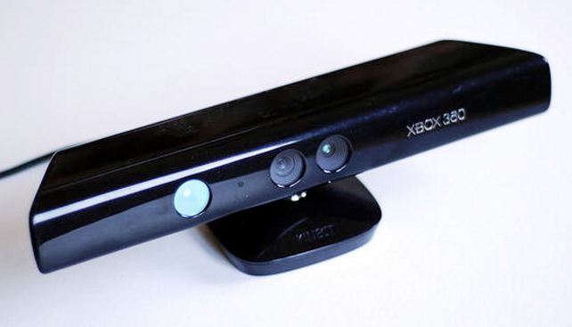
The Kinect sensor is a popular game controller for Microsoft's gaming system, XBox. This was the first inexpensive commercial sensor to allow the user to interact with a gaming console through physical gestures, and spoken commands.


Figure 2: A Kinect (image courtesy: Arduino and Kinec Projects).

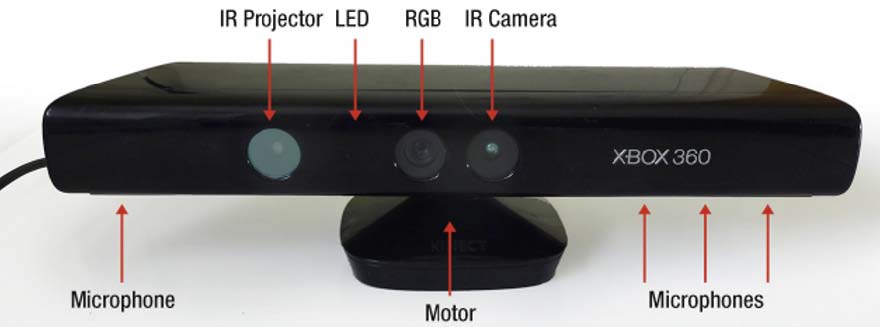
It hosts a number of other sensors and devices. Some of these are:
  • an RGB camera (640x480 pixel),
  • a depth sensor:
    • an infra-red laser projector, and
    • an infra-red CMOS sensor,
  • a multi-array microphone,
  • a three-axis accelerometer, and
  • a servo for tilting the device.

Figure 3: Kinect hardware (image courtesy: Arduino and Kinec Projects).

In this project, however, we are mainly interested in the depth sensor. We will explain why will not use the RGB camera in Section Kinect Tracker.

Development Environment for the Kinect

We will briefly describe how one can get started with the Kinect sensor. The sensor requires a driver to send depth data to a workstation. The required driver and SDK for Windows systems can be downloaded from here. And, for Linux based systems, the required driver and also an SDK can be downloaded from OpenKinect's Main page.

The easiest and probably the simplest way to get started is to use Processing. It is both a language -- a variant of JAVA and an IDE for development. Next, a Processing library for the SDK needs to be installed. SimpleOpenNI and OpenKinect are two such libraries. One advantage of Processing and these two libraries is that the same Processing source code works both in Linux and Windows based systems without any modification.

Software Components for the Base-station

We require two different software modules for the base-station. These modules are:
  1. Object tracker, and
  2. Trajectory transmitter.
The object tracker module computes the current positions of the satellite stations using the depth map data provided by the Kinect sensor. The object tracker is also responsible for computing the required radii and speeds for each of the satellite stations. And, the trajectory transmitter informs the the satellite stations of their next heading in terms of radius and speed. In addition, the object tracker and the trajectory transmitter communicates with each other over a Serial Communication (COM) port.

The object traker module runs on a workstation. We will describe in detail about the object tracker in Section Kinect Tracker. However, the trajectory transmitter runs on an XPlained 1284p micro-controller board. The transmitter is implemented using the RTOS we developed in Project 3.

Software Components for the Satellite-stations

The software component for the satellite stations is very simple. This module listens for two pieces of information, radius and speed, from the base-station. Upon receiving these, the module then sends the required drive command to the Roomba robot. An example implementation of how to drive Roomba robots using a micro-controller board can be found in Project 1 and in Project 2.

Formation Control

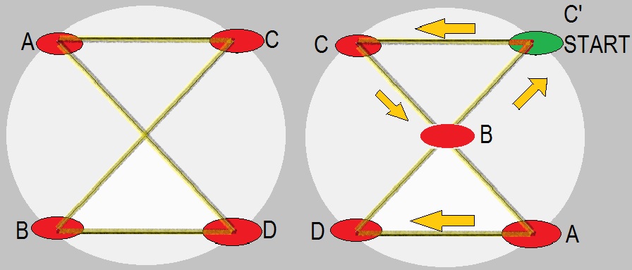
In Section Circle and in Section Spiral 1, we have shown our desired coordinated motion for the satellite-stations. We expect that the stations need to be positioned on equally spaced points of a circle and oriented along the tangent direction of the circle.

Upon achieving the desired configuration, the stations can then drive using the same radius and speed command. Our expectation is shown in Figure 4. An expected coordinated diamond motion using different radius but similar speed for each of the stations is shown in Figure 5.


Figure 4: Initial configuration and expected circular coordinated motion.


Figure 5: Initial configuration and expected diamond coordinated motion. We define the diamond motion as a simplification for a motion along the locus of the Lemniscate of Bernoulli.

System behaviour using Message Sequence Chart

We now describe the overall system behaviour using the message sequence chart shown in Figure 6. We expect that the implemented system will find the the required corner (equally spaced points) in a reasonable amount of time. When all the stations are able to position themselves, the base system then periodically instructs their intended speed and radius.


Figure 6: Message sequence chart for our proposed system.