Context Switch

In this page we will describe the data that constitute the context of a task in an 8 bit AVR ATmel MCU. We will then show how the kernel switches the contexts of tasks to provide concurrency.

In general, the scheduler maintains a queue of tasks for each priority level (e.g., System, Periodic, RR). Based on some scheduling policies (fixed or dynamic) the scheduler may decide to suspend a task and resume another task, that is, switch contexts to run a different task. In this RTOS, a context switch occurs in the following cases:
  • an RR task pre-empts the idle task,
  • an RR task finishes its quantum (allotted time of execution),
  • a scheduled Periodic task pre-empts an RR or the idle task,
  • a Periodic task voluntarily relinquishes the CPU,
  • a System task becomes ready and pre-empts a running non-system task (e.g., Periodic, RR, idle)
  • an RTOS tick occurs, and
  • a hardware interrupt pre-empts a running task.
Note that a context switch because of a hardware interrupt takes place out of the control of the RTOS. Usually, this is automatically done by the hardware. However, this context switch implicitly assumes that the interrupted task will get the context back when the Interrupt Service Routine finishes servicing this interrupt. Therefore, hardware only saves and restores the registers that it uses during the ISR routine. This is done intentionally so that an ISR finishes as fast as possible.

Context Switch in an ISR

The following assembly listing shows the External Hardware Interrupt, INT2, for Xplained ATmega 1284p that we have written in Project 2 in order to detect rising and falling edges of the PIR sensor. Notice the Lines 0-12 and Lines 40-50 where only partial context saving and restoring occurs, respectively.


Disassembly of section .text.__vector_3:

00000000 <__vector_3>:
   0:	1f 92       	push	r1
   2:	0f 92       	push	r0
   4:	0f b6       	in	r0, 0x3f	; 63
   6:	0f 92       	push	r0
   8:	11 24       	eor	r1, r1
   a:	0b b6       	in	r0, 0x3b	; 59
   c:	0f 92       	push	r0
   e:	8f 93       	push	r24
  10:	ef 93       	push	r30
  12:	ff 93       	push	r31
  14:	80 91 69 00 	lds	r24, 0x0069
  18:	84 ff       	sbrs	r24, 4
  1a:	00 c0       	rjmp	.+0      	; 0x1c <__vector_3+0x1c>
  1c:	81 e0       	ldi	r24, 0x01	; 1
  1e:	80 93 00 00 	sts	0x0000, r24
  22:	e9 e6       	ldi	r30, 0x69	; 105
  24:	f0 e0       	ldi	r31, 0x00	; 0
  26:	80 81       	ld	r24, Z
  28:	8f 7e       	andi	r24, 0xEF	; 239
  2a:	80 83       	st	Z, r24
  2c:	11 9a       	sbi	0x02, 1	; 2
  2e:	00 c0       	rjmp	.+0      	; 0x30 <__vector_3+0x30>
  30:	10 92 00 00 	sts	0x0000, r1
  34:	e9 e6       	ldi	r30, 0x69	; 105
  36:	f0 e0       	ldi	r31, 0x00	; 0
  38:	80 81       	ld	r24, Z
  3a:	80 61       	ori	r24, 0x10	; 16
  3c:	80 83       	st	Z, r24
  3e:	11 98       	cbi	0x02, 1	; 2
  40:	ff 91       	pop	r31
  42:	ef 91       	pop	r30
  44:	8f 91       	pop	r24
  46:	0f 90       	pop	r0
  48:	0b be       	out	0x3b, r0	; 59
  4a:	0f 90       	pop	r0
  4c:	0f be       	out	0x3f, r0	; 63
  4e:	0f 90       	pop	r0
  50:	1f 90       	pop	r1
  52:	18 95       	reti


There are situations when an RTOS needs to be in control of an ISR so that instead of returning the context to the interrupted task the ISR restores the context of the kernel. In particular, during an RTOS tick, the context of the kernel is restored instead of the context of the interrupted task. However, this context switch needs to be complete instead of a partial one.

Context Switching in an RTOS Tick

The following listing shows how we implemented the RTOS tick. Notice, how the prototype (function signature) is defined with two attributes, namely, signal - to denote that this is an ISR and naked - to request the compiler not to generate any context restoring and context saving codes. There is, however, one subtle detail that we need to take care of if we save and restore context ourselves. Saving the context in an ISR is not enough. Since, interrupt is automatically disabled inside an ISR by the hardware, the saved context has interrupt disabled. We, however, know for sure that interrupt was enabled in the interrupted task -- which resulted in this interrupt being generated. Therefore, we need to save the status register with interrupt bit enabled; see macro definition SET_I_BIT(). This, on the other hand, is not necessary when we perform context switching in a non-ISR routine.
void TIMER2_COMPA_vect(void) __attribute__( (signal, naked));
void TIMER2_COMPA_vect(void)
{
	SAVE_CONTEXT_TOP();
	SET_I_BIT();
	SAVE_CONTEXT_BOTTOM();
	
	/* TIMER code will go here */
	
	/* Timer code will end in the line above */
	RESTORE_CONTEXT();
	asm volatile ("ret\n"::);
}


Context of a Task

At this point, we state what constitute a context for a task. For 8 bit AVR ATmel MCUs the context for a task is comprised of the following:
  • the general purpose registers r0 to r31,
  • the Status register (SREG),
  • the Program Counter register (PC),
  • the Stack Pointer register (SP), and
  • the program stack.
The program counter stores the address of the next instruction to be executed. Program counter is automatically stored by the hardware. We will talk more about this shortly. The program stack is a contiguous region of the memory (SRAM) where the context of this function and the nested functions will be saved. The Stack Pointer register points to a location in the program stack in which next pushed item will be placed and below which is the location of the item to be popped next.

Context Switching between two (non-ISR) Tasks

We will now describe how context switching occurs in this RTOS. This part of the discussion is inspired by similar discussion at FreeRTOS RTOS Implementation.


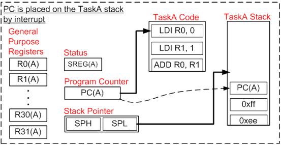
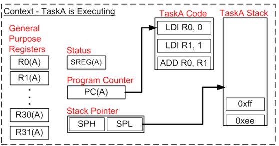
  1. Assume for the moment that a task TaskA is currently running.


    Figure 1: Context of a running task TaskA. (Image source: www.freertos.org.)


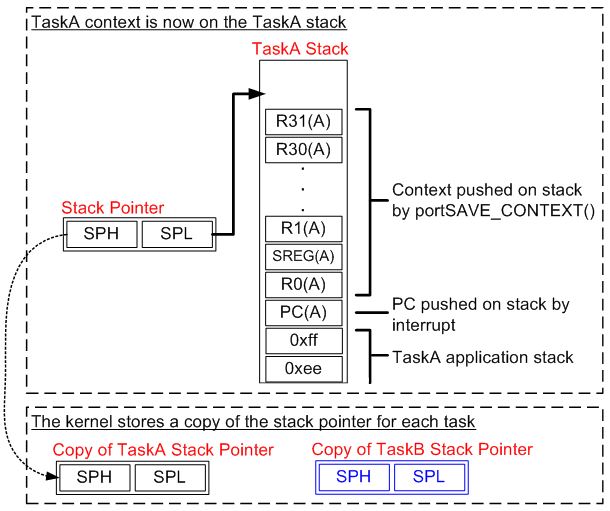
  2. Then RTOS tick occurred that generated a hardware interrupt. The interrupt automatically saves the Program Counter register that pointed to the next instruction of TaskA in TaskA's program stack.


    Figure 2: Program Counter is automatically saved by the hardware in TaskA's stack when the interrupt occurred.(Image source: www.freertos.org.)


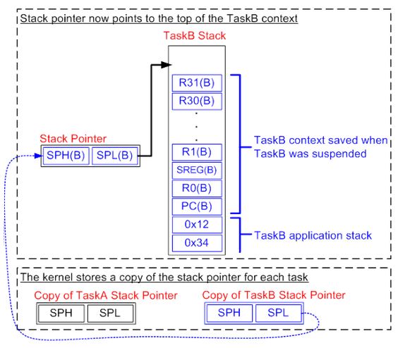
  3. Next, imagine the timer code (Lines 4-6, given above) that saves the context is being executed. Also, the stack pointer of TaskA is stored by the kernel.


    Figure 3: Context of TaskA being saved in the program stack of TaskA. (Image source: www.freertos.org.)


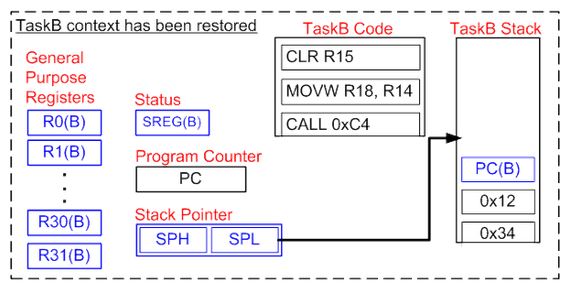
  4. Then, the stored stack pointer of TaskB (in our case the kernel) is copied onto the Stack Pointer (SP) register of the MCU. At this moment the stack pointer is now pointing to the top of the TaskB's (kernel's) context.

    Figure 4: MCU Stack pointer now points to the top of the context of TaskB. (Image source: www.freertos.org.)


  5. Now, imagine the timer code (Line 11, see above) that restores the context of TaskB is being executed.


    Figure 5: Context of TaskB (kernel) is restored. (Image source: www.freertos.org.)


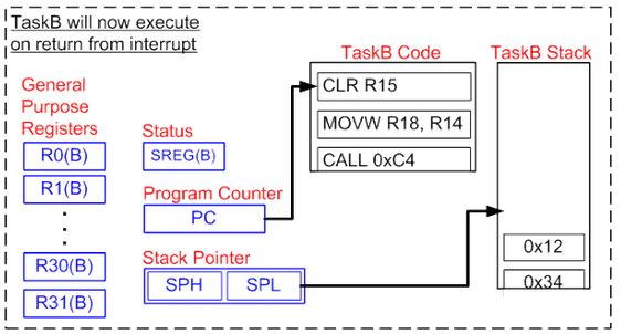
  6. Program Counter register is restored automatically by the hardware. TaskB (kernel) now resumes executing.


    Figure 6: TaskB (kernel) begins executing now. (Image source: www.freertos.org.)


Context Creation

The method described above assumes that the contexts of the tasks involved in the switching have been properly created. That is, in order for context switching to take place correctly between a running a task and a task that will be run for the first time, the context of the later task should be properly created at the time when the task is created. Next, we show how to create the context of a task when it is being created by another task. The listing below shows part of our context creation routine.
static task_descriptor_t* new_task;
static void kernel_create_task_context()
{
	/* Task terminate */
	new_task->stack[MAXSTACK-1] = (uint8_t) (uint16_t) Task_Terminate;
	new_task->stack[MAXSTACK-2] = (uint8_t) ( (uint16_t) Task_Terminate >> 8);
	/* address of the task */
	new_task->stack[MAXSTACK-3] = (uint8_t) (uint16_t) kernel_task_create_args.f;
	new_task->stack[MAXSTACK-4] = (uint8_t) ( (uint16_t) kernel_task_create_args.f >> 8);
	/* r31 is saved first in stack[MAXSTACK-5] */
	/* SREG is saved in stack[MAXSTACK-6] */
	new_task->stack[MAXSTACK-6] = _BV(SREG_I);
	/* r1 is the zero register */
	new_task->stack[MAXSTACK-37] = (uint8_t) 0;
	/* r0 is at new_task->stack[MAXSTACK-37] */
	/* stack pointer now should point to new_task->stack[MAXSTACK-38] */
	new_task->sp = &(new_task->stack[MAXSTACK-38]);
	
	/* for memory protection 
	four bytes will be written with special bit patterns.
	If these patterns are over written then stack
	overflow has occurred. Not a full-proof method.
	*/
	new_task->stack[3] = 0b01010101;
	new_task->stack[2] = 0b11001100;
	new_task->stack[1] = 0b00110011;
	new_task->stack[0] = 0b10101010;
}


Figure 7: Context of a newly created task.


Figure 7 shows the memory layout of the program stack of a newly created task. The bottom two bytes contain the address of the Task Terminate - to return the task resource to the dead pool when this task finishes. Also, notice the top four bytes. These four bytes and the bottom two bytes mentioned above should remain unchanged throughout the entire life time of the task. These bytes are, therefore, checked every time when context switch with this task takes place. We should mention at this point that not all stack overflow and underflow will be caught by this method.

We would also like to point out the value of the Status Register in the program stack; see cell number 250. At the time of the creation of the task, we save the Status Register with its interrupt bit enabled. This is very crucial. RTOS tick and all other hardware interrupts will not be generated during the entire time of this task if the interrupt bit is not enabled at the time of task creation. If this task happens to be an RR task that never blocks or voluntarily relinquishes the CPU, the system will continue to run this task forever.